Table relationships
To understand how the relational model influences our databases, let’s take the examples of two tables from a college database.
The first table shows a list of students along with their assigned student and course identification numbers. The second table list courses that students can study along with the ID for each course and its department.

The big question in this example is which student is studying what course? Is each student studying one or multiple courses? These are basic examples of why it’s important to structure and connect tables correctly.
There are three types of relationships between any two tables in a relational database:
- one-to-many
- one-to-one
- many-to-many
One to many relationship
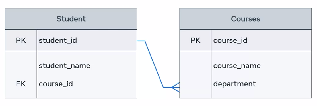
In a one-to-many relationship, a record of data in a row of one table is linked to multiple records in different rows of another. The student table, a student with the idea of one is enrolled in two courses on the course table. So one-to-many relationship can be drawn between these tables.

This relationship can also be illustrated in a basic entity relationship diagram, or ERD. A student is enrolled in many courses using shapes and symbols.

The diagram depicts the two entities, student and course, in rectangle shapes with enrolled to describe the relationship in a diamond shape. Many is depicted using the Crow’s foot notation symbol.
The relationship can also be illustrated using a more complex ER-Diagram that depicts keys. Course ID in the student table is a foreign key or FK. This references the primary key or PK course ID column that exists in the course table.
One to one relationship
In one-to-one relationships, one single record of one table is associated with one single record of another table.
To demonstrate this relationship, I’ll use two new tables. One that end lines key information about the staff in each college department. The other is the department location table that records key data where the location of each department on campus.

In this instance, each department head is in one department building on the college campus. Each staff member from the department staff table is associated with one record from the department table.
These relationships can also be depicted in an ER diagram as one department head leads one department.

Many to many relationship
This type of relationship associates one record of one table with multiple records of another table. The same relationship also works in the other direction.

In this example, the student, Maurice Doyle, is undertaking two research projects and each project is supervised by different staff member. Likewise, one staff member can supervise or collaborate with multiple students on their research projects.
These relationships can also be depicted in an ER diagram as many students are supervised by many staff.

Relational model
You are already familiar with table relationships, one of the main concepts behind the relational database model. In this reading, you’ll find out more about the relational database model. Though it was introduced a long time ago, it is still the most widely used data model for commercial databases.
What is the relational model?
The relational model is built around three main concepts which are:
- Data,
- Relationships,
- and constraints.
It describes a database as “a collection of inter-related relations (or tables)”. It is still a dominant model used for data storage and retrieval. In essence, it is a way of organizing or storing data in a database. SQL is the language that’s used to retrieve data from a relational database.
Fundamental concepts of the relational model
Relation
A relation represents a file that stores data. It’s also known as a table. Within a table there are rows and columns. Each row represents a group of related data values. A row, or record, is also known as a tuple. Columns in a table are also known as fields or attributes. These columns define or describe a row. Therefore, a record or a row consists of a set of attributes.

Column
A table stores pieces of data or facts as columns. In other words, the principal storage unit of a database is a column (attribute). When determining the columns for your table, think about the pieces of data that need to be stored within that table. Each column is a generic representation of the piece of data that needs to be stored. Each table cell that becomes a part of a row will have a specific instance of a piece of data.
| ID | First Name | Last Name |
|---|---|---|
| 1 | John | Smith |
| 2 | Mish | Azerrad |
| 3 | Peter | Klien |
For example, ID, First Name and Last Name are columns. The ID numbers, first names and last names are instances or pieces of data that are stored in those columns. Also, every column has a specific data type, which could be numeric, text, or date.
Domain
The domain is a set of acceptable values that a column is allowed to contain. The domain depends on the data type of the column. Namely whether it is numeric, or text based. The domain of ID has a set of acceptable and possible values that are numeric such as1, 2 and 3. The domain of First Name has a set of acceptable and possible values that are text based, which is people’s first names. In the ID column, it’s not possible to store values such as “John” or “001”. Similarly, the First Name column can’t accept any numeric pieces of data.
Record or tuple
A record, also known as a tuple, is a row within a table. If a table has columns for ID, First Name and Last Name, then one record or tuple would have one person’s ID, first name and last name. Another record would have another person’s full personal information.
Key
Each row or tuple has one or more attributes, known as a relation key, that can uniquely identify a specific row. This is also known as the primary key.
Degree
Degree is the number of columns or attributes within a relation. A student table that stores the student’s name, address, phone number and email address would have a degree of four.
Cardinality
Cardinality refers to how many records there are within a particular table in a database. If you have 100 students in your student table, with all their information organized into individual rows, then that table has a cardinality of 100.
What are constraints?
In the relational model, every relation needs to meet three conditions. These three conditions must be met for a relation to be valid. They are called relational integrity constraints and they are:
- Key constraints
- Domain constraints
- Referential integrity constraints
Key constraints
The key constraint revolves around the key attribute(s). In the relational model, a key attribute is an identifier that can be used to refer to a record. It must also be unique for each record. For example, you can use the Student ID in the student table as the key. This means that there can’t be two students with the same Student ID. If so, it would be invalid and cause an issue when it comes to accessing or retrieving the data. Also, a key attribute cannot have NULL values. This is the requirement that should be met by the Key constraint.
Domain constraints
Domain constraints are all about the requirement of inserting values that have a valid data type. There are a variety of data types that can be included within a table, namely numeric, text and data, in the case of the example. If an attempt is made to store an incorrect data typed value to an attribute, it’s declared a violation of domain constraints. For instance, if an attribute requires a numeric value to be entered, and the value you are attempting to enter uses letters instead of numbers, then it would be invalid.
Referential integrity constraints
A database has multiple tables that refer to one another. Referential integrity constraints are based on the concept of foreign keys. A foreign key is a key attribute present in a table, which is also a primary key of another table to which it needs to be linked. Through this key, it references the other table to which it’s related. For example, the order ID is present in the Order_Item table as a foreign key, which is also the primary key of the order table. So, the order table and the Order_Item table are related to each other because the Order_Item table references the order table via the order ID attribute. The referential integrity constraint states that if a relation refers to a key attribute of another relation, then that key element must exist. In other words, there must be matching values in the two tables for that attribute.
Types of relationships
In the relational model, there are three types of relationships that can exist between tables.
- One-to-one
- One-to-many
- Many-to-many
One-to-one
In order to understand one-to-one relationships, let’s take the example of two tables: Table A and Table B. A one-to-one (1:1) relationship means that each record in Table A relates to one, and only one, record in Table B. Likewise, each record in Table B relates to one, and only one, record in Table A.
Here is a diagram that illustrates the example:

Here, every country has one, and only one, capital. And every capital belongs to one and only one country.
One-to-many
If there are two tables, Table A and Table B, a one-to-many (1:N) relationship means a record in Table A can relate to zero, one, or many records in Table B. Many records in Table B can relate to one record in Table A.
Let’s examine the following relationship between customers and orders.

Here, each customer can place many orders. Many records in the order table can relate to only one record in the customer table.
Many-to-many
If there are two tables, Table A and Table B, a many-to-many (N:N) relationship means many records in Table A can relate to many records in Table B. And many records in Table B can relate to many records in Table A. Let’s examine this example of many-to-many relationship between customer and product with the use of a diagram. In the diagram, customers can purchase various products, and products can be purchased by many customers.

Usually, many-to-many relationships are not kept in a data model. They are broken down into two one-to-many relationships by introducing a junction or middle table.
To conclude, there are many benefits to the relational database model. This includes the ability to design and develop a meaningful system of information, and the ability to access and retrieve every single piece of data stored in the database.
Primary key
By now you’re probably familiar with querying values or records within database tables. But how do you query specific records and values if they’re duplicated across the table. When you come across obstacles like these, you can use keys as your solution.
You may have encountered several examples of primary keys during this course. In these examples, you saw that they’re using tables as unique method to identify a record and prevent duplicates.
Let’s take an example of a student table with five attributes, ID, name, date of birth, email, and grade. How could we identify a specific student to enter their grade? The student Mary, on row 2.
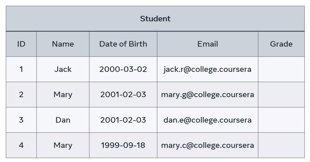
All you need to do is find the unique ID of Mary to identify a record of her data. However, in this example, you can’t use the student name column because there are two students in the table called Mary. You can’t use the date of birth either because another student in a table called Dan has the same birthday.
Neither of these records are unique to Mary, so what’s the best approach? The solution is to locate a candidate key. This is an attribute that’s unique to each row of the table and I cannot have a null value. In other words, it cannot be empty.
In this example, there are two possible candidate keys, the student ID and the student email. Both rows contain a unique value for each student, so either one can be used as a primary key.
Let’s assign the student ID as the primary key. Whichever column you reject as the primary key becomes the alternate or secondary key. In this instance, the email column is a secondary key.
But what happens if you can’t locate a unique value within the table? Maybe all rows of duplicated values.
In this instance, you can create a composite primary key, this type of key in the combination of two or more attributes.
Let’s take the example of the delivery department of an online store. They have a delivery table, the tracks and the deliveries placed by their customers. However, there’s no single column with unique values in each row. No column can be considered as the primary key.
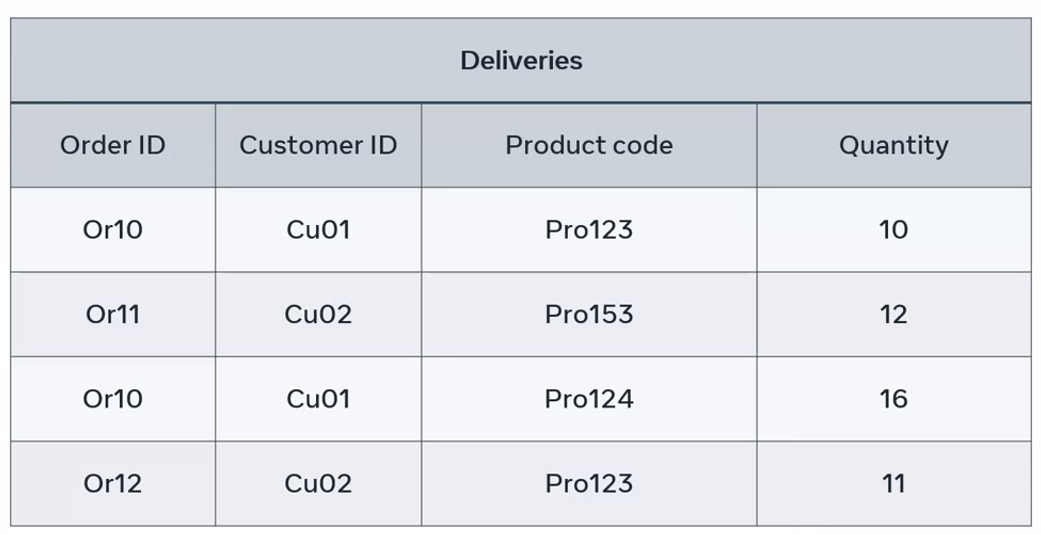
In this case, the best approach is to combine the customer ID and project code columns to create a unique value for each specific record of data. With these columns, you can determine which customer ordered what product so together, these columns become the composite primary key.
Foreign key
Imagine a scenario where a bookstore has a database that contains two tables. Customer table to track customer information, and an order table to track customers orders. But how can they determine which customer made which order?
The solution is to add a customer ID column into the order table column as a foreign key.
Foreign key
A foreign key is one or more columns used to connect two tables in order to create cross-referencing between them. By foreign developers mean external. The foreign key in one table, we’ll refer to an external or foreign column in another table.
Let’s find out more about how foreign key works by exploring the tables from the database of an online store. The store is customer table contains information about the customer’s name and address. While their order table contains information about each customer’s order date and status. The issue is how to connect these tables to make sure that each order is associated with the right customer.
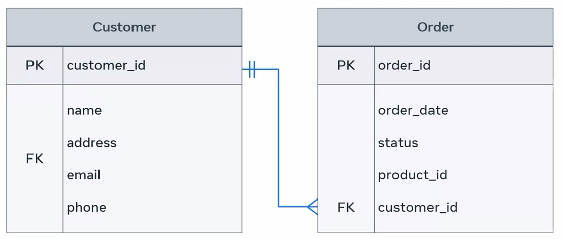
Establishing this connection is important so that you can process, and deliver orders to the right customers, update order details, or cancel orders if required. A foreign key is a great method of establishing a relationship between these tables so that these other tasks can be carried out.
In this diagram, the order table relates to the customer table by including the customer ID attribute, and defining it as foreign key inside the order table. The relationship between these two tables is one-to-many.
NOTE
One-to-many means that each customer may have many orders, but each order must refer to one single customer only. This means there must be a customer record available in the customer table before any order can be made. But it is not necessary to have an order once a new customer is created.
Therefore, the customer table represents a parent table and the order table represents a child table. This means that the parent can exist, and the child may not exist. But the opposite scenario cannot occur.
It is also possible for table to have more than one foreign key. Each will be used to connect the referencing or child table with other referenced or parent tables. In this case, you’ll have multiple parents to the same child.
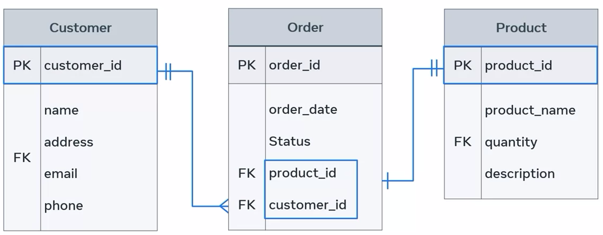
The order table now has two foreign keys. One foreign key links it with the customer table via the customer ID, and the other links it with the product table via the product ID. The relationship between these tables is one-to-one. Each order must be related to a specific product record, and each product might be related to an order record, but doesn’t have to be.
For example, you can receive a new product in your inventory, but no customer has placed an order on it yet. If an order has not been placed in this product, then it’s not related to any order yet.
This then raises the question, who is the parent, and who is the child?
The answer is that there are now two parents, the customer and the product tables, and there’s one child, which is the order table.
Keys in depth
In this reading, you’ll explore the concept of keys in more depth, so you have a better understanding of how to choose a primary key from a list of “candidate keys”, and how to connect tables together with foreign keys in SQL.
A relational database is a collection of data that is managed and maintained in a database management system such as Oracle or MySQL. A relational database enables you to retrieve every single piece of stored data. This can be done by specifying:
- the name of the target table (or tables),
- the name of the required column (or columns),
- and the primary key of the table.
In a relational database, the primary key can be selected from any candidate key attribute that contains a unique instance value in each row of the table.
Review the following vehicle table. Can you identify the candidate key attributes?
| Vehicle ID | Owner ID | Car plate number | Owner phone number |
| D01 | Ow01 | PL02NY | 0738297294 |
| D02 | Ow02 | SN02L2 | 0725021582 |
| D03 | Ow03 | PK02L2 | 0765021583 |
This table includes three candidate keys:
- the vehicle ID,
- the car plate number,
- and the owner’s phone numbers.
Each of these three keys holds unique values in the related column in all rows. Therefore, each of those attributes can potentially act as a primary key column for the vehicle table and could be used to uniquely identify each record in the table. You might notice that there are unique values in all rows that belong to the owner ID. So, is the owner ID a fourth candidate key?
Well, it is correct that the owner ID column has unique values in all rows of the table in the given example. However, it’s possible that the same owner may buy another car and will then have multiple cars. So, it’s not a good idea to choose this column, because if someone owns multiple cars then the owner ID will no longer be unique. For example, if an owner buys three cars, then their owner ID repeats itself three times in the table. This means that it’s no longer unique and thus cannot be chosen as a primary key.
But which of the three attributes would be the best candidate to act as a primary key? The vehicle plate number could be problematic. The owner might choose to change the vehicle plate number by purchasing a private plate number. In this instance, the vehicle plate number associated with the owner would change. This would require updating the plate number wherever it exists in the database. However, in case none of the values are updated, or if they’re updated with a wrong number, this will cause confusion and can sometimes even cause serious errors and problems.
Similarly, the owner phone number can’t be considered as a primary key because this candidate key value may change if the owner changes their phone number. This will then lead to the same type of problem that you could encounter with the number plate candidate key.
When you design a table in your database, you must make sure to choose a candidate key with a value that cannot change. The vehicle ID candidate key is unique and not expected to change so it should be your primary key. The entity relationship diagram below shows the primary key of the table in bold and underlined.

Do you know how to create this table with SQL inside a database called automobile? If yes, please create it now, and remember to define the vehicle ID as a primary key.
Otherwise, complete the following step-by-step instructions inside MySQL in your machine on the Coursera platform.
Create the database
Inside the terminal, write the “CREATE DATABASE” command followed by the name of your new database. In this case, the database name is named “automobile”. Finally, add a semi-colon at the end of the statement and click enter on the keyboard to execute the query.
CREATE DATABASE automobile;
Below is a screenshot of the create database statement inside the terminal.

Well done, you have now created the automobile database.
Create a table
Use the database to create the vehicles table inside the automobile database. You need to choose the automobile database first by typing the following SQL syntax:
Use bookshop;
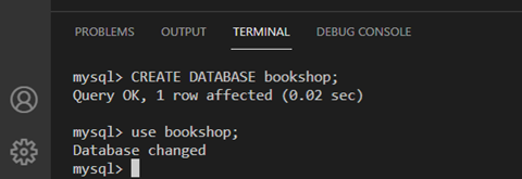
Write the create table statement
To create the vehicle table, write an SQL statement that contains the CREATE TABLE command followed by the name of the table (vehicle in this case) and open parenthesis to define the table’s columns including the vehicle ID, owner ID, plate number and phone number. Of course, each column should be assigned a suitable datatype, as shown in the previous ER diagram.
Once all required columns have been defined, you must add a closing parenthesis and a semi-colon at the end of the SQL statement as follows:
CREATE TABLE vehicle( vehicleID varchar(10), ownerID varchar(10), plateNumber varchar(10), phoneNumber INT);
Click enter to execute the SQL statement. The output result is displayed below.

To show the table you have already created, you can type the following syntax:
Show tables;
The vehicle table is displayed inside the automobile database.
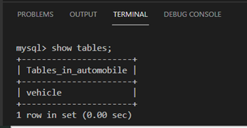
To show the structure of the vehicle table, you can type:
Show columns from vehicle;
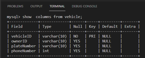
Now any candidate key that has not been chosen to act as the primary key of the vehicle table is called an alternate key. That’s the plate number and phone number.
Also, it’s important to remember that a primary key can be composed of one single simple attribute or multiple attributes (a composite key), which is composed of two or more attributes that form a unique value in each row of the table. This usually happens when a single attribute cannot be found to act as a primary key. If you have any doubt about what a composite key is and how to create it, please review the primary key video where the concept was discussed in detail.
Now let’s build another table to maintain data about the vehicles’ owners. This table includes information about the owner’s name and address as illustrated below.
| Owner ID | Owner name | Owner address |
| Ow01 | Amjad Omer | 110, Elephant Way |
| Ow02 | Hans Henderson | 120, Dragon Way |
| Ow03 | Paulo Galdames | 130, Giraffe Avenue |
The owner ID is the primary key in this table, as it will always be unique. Whereas the owner’s name could be the same for different owners, and the owner address could be the same for different owners living at the same address. This would violate the uniqueness requirement for the primary key.
Now create the Owner table in the automobile database. Remember to declare the ownerID as the primary key of the table.
In case you have any difficulty with this task, write the following SQL statement in the terminal section and click enter button to execute the query.
CREATE TABLE Owner(ownerID VARCHAR(10), ownerName VARCHAR(50), ownerdrerss VARCHAR(255), PRIMARY KEY (ownerID));
Let’s now examine the structure of the owner table by executing the following SQL query:
Show columns from vehicle;
The output of the query in the image below depicts the owner table structure, including the columns or fields, data types, key and default values.

By now you have two tables created in the automobile database. The vehicle table contains information about the vehicle ID, owner ID, plate number and phone number. Whereas the owner table contains information about the owner ID, owner name and address.
You may have noticed that the owner ID is a common attribute, as it exists in both tables. However, the key difference is that it is a primary key in the owner table. This means it must be unique in each row of the table. Yet it might be duplicated in the vehicle table, because the same owner might have multiple vehicles. This means that the owner ID in the vehicle table is a suitable choice for a foreign key that connects the vehicle table with the owner table as shown in the following ER diagram.

This diagram shows the cross-reference between the two tables. The owner ID column represents the foreign key in the vehicle table that refers to the external primary key column in the owner table. This ensures that each vehicle is associated with the right owner. Also, according to the diagram, the relationship is one-to-many, where each owner may own many cars.
To create this relationship in the actual database you need to modify the vehicle table structure to make the owner ID a foreign key. This can be done by using the “ALTER” command to change the structure of the vehicle table. You can also use the “ADD” command to define the owner ID as the foreign key. Finally, you can use a “REFERENCES” keyword to reference it with the primary key in the owner table.
ALTER TABLE vehicle ADD FOREIGN KEY (ownerID) REFERENCES owner (ownerID);
Once the above alter statement is executed, type the following SQL statement to show the new structure of the vehicle table:
Show columns from vehicle;
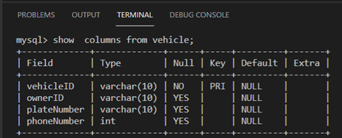
You will notice that the owner ID key has been changed into a MUL key, which is one of the three possible values for the “key” attribute in MySQL.
- PRI comes from primary; this means it’s a primary key.
- UNI comes from unique; this means it’s a unique key.
- MUL comes from multiple. If the key is MUL, it means that the related column is permitted to contain the same value in multiple cells of that column.
In this reading, you learned how to choose the primary key from a set of candidate keys. In addition, you learned how to alter the structure of the table to associate two tables by using the foreign key.
Finding entitites
When building a database, there’s often a lot of different tables that you’d need to consider including. But how do you determine what to include and what to exclude? The answer is to identify the entities you’re interested in maintaining data on.
Entity
An entity can be described as an object that has properties which define its characteristics. An entity can be anything that represents a single object in a database, such as a place or a person.
In a relational database system, each interesting object in a project could be considered an entity. For example, a customer or individual.
An entity in a table is comprised of rows and columns created in database management systems such as MySQL.
Example:
Example of a table that holds delivery records for the database of an e-commerce store:
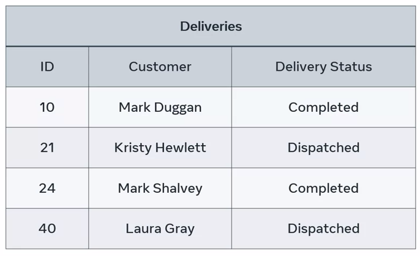
The table name represents the entity name, deliveries, and each column represents the entity-related attributes. The system holds customer or entity relevant attributes such as ID, name, and delivery status details. These attributes hold relevant data about the table entity. Each instance of the customer entity in this e-commerce system contains a record of data about each customer.
But there are also different types of attributes in a relational database system. These include:
- simple attributes
- composite attributes
- single-valued attributes
- multi-valued attributes
- derived attributes
- key attributes
Example: Student table
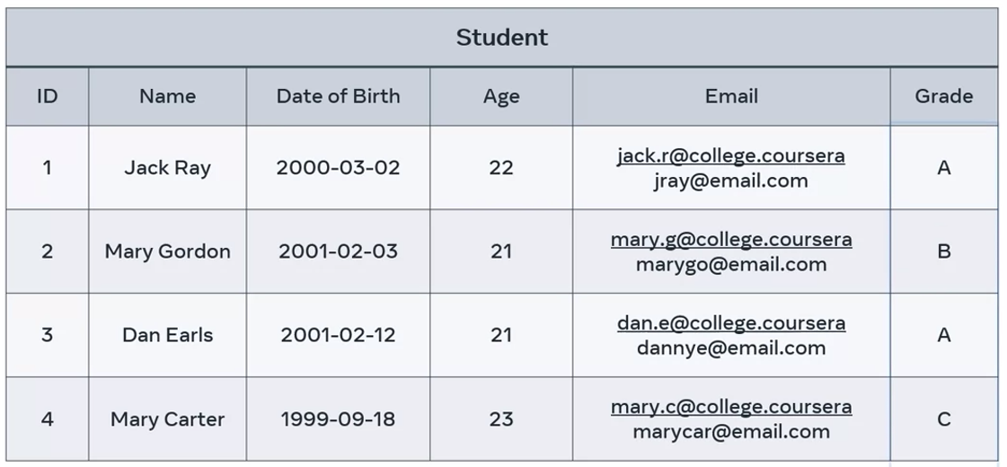
- A simple attribute is an attribute that cannot be classified further. In the example of the student records, the grade values cannot be classified further.
- A composite attribute is an attribute that can be split into different components. For example, the name value of each student could be split into sub-attributes such as first and last name.
- A single value attribute can only store one value. In the student table example, the date of birth column can only contain one value per student. These values can be defined as a single-valued attributes.
- With a multi-valued attribute. The attribute can store multiple values in the field. For example, the student email column could hold more than one email per student; a college email address, and a personal email address.
WARNING
However, this practice should be avoided in a relational database.
- A derived attribute is where the value of one attribute is derived from another. In the student table, the age of each student can be derived from the respective date of births.
- Finally, there’s the key attribute. This is a field that holds a unique value used to identify unique entity record. A good example, are the values contained in the student ID column. Each ID is a unique value which can be used to obtain data about a specific student.
TIP
Remember that there’s no point in considering entities or attributes that will not be used in your project. You only need to capture data in your database system that helps the users of your system complete certain tasks and activities.
Entity relationship diagrams (ERD)
This reading covers the Entity Relationship Diagram (ER-D) and demonstrates how to use it to support the design of a relational database.
The relational database model organizes information into tables to ensure a good data structure to maintain consistency and accuracy, which makes the design of the tables and their relationships very crucial. The relational database design is very well connected with the entity relationship modelling process including entities, attributes and relationship identification and definition. The entity-relationship diagram (ER-D) is commonly used to represent and document the entity relationship models.
The use of entity relationship diagrams helps to provide the big picture of your database. It also ensures the data requirements and operations are well defined and documented in your project. In addition, the ER-D represents a blueprint that guides database developers through the implementation of the actual database in a relevant database management system such as Oracle and MySQL.
The entities, attributes and relationships between entities can be shown in a variety of diagrammatic formats in the ER diagrams. In this reading, you’ll review the most used shapes and symbols.
Entity representation
In the ER-D, a box with two compartments is used to represent the entity and its related attributes. The top compartment represents the entity name, and the bottom compartment includes the related attributes.
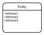
For example, a college enrollment system contains a database with information about the students, and the courses available in each department.
In this case, you can have three entities represented in three separate boxes:
- the student entity,
- the course entity,
- and the department entity.

There’s no point in considering entities or attributes that will not be used in your project. You should only capture data that helps the users of your database system to complete certain tasks and activities.
Relationship representation
The ER diagram uses different styles of lines to define the distinct types of relationships between entities. The line style depends on the cardinality of the relationship, which refers to the number of elements in a set of data as clarified in the following three cases.
1:1 (one-to-one): The ER-D uses a straight-line representation for a one-to-one cardinality relationship. For example, each passenger on a train should have only one ticket.

1:N (one-to-many): The ER-D is a straight line with a crow’s foot notation on one side only to represent a one-to-many cardinality relationship. For example, one parent can have many children.

M:N (many-to-many): The ER-D is a straight line with crow’s foot notations on both sides of entities to represent a many-to-many cardinality relationship. For example, many players play many games.

Based on this explanation, how would you depict the relationship between the student, course, and department entities introduced earlier in the college enrolment system example? Remember that many students may enroll in one course, and one department may offer many courses.
In this example, you can use a one-to-many relationship where the crows-foot notation is used to show that “many students” are enrolled in one specific “course”, and “many courses” belong to one specific department.

Attributes representation
Each entity has a set of attributes that hold relevant information about it. Each attribute must be defined with a data type.
In the college enrolment example, you can list the following attributes followed by relevant data types:
- The department attributes: department number, department name and head of department.
- The course attributes: course ID, course name, and course credits.
- The student attributes: student ID, name, and date of birth.
The three entities can be listed as three separate tables.

However, you need to add the department number to the course table as a foreign key in order to link the courses with the departments.
Similarly, you need to add the course ID to the student table as a foreign key in order to link the students with the courses. The final college enrolment entity relationship diagram is then three separate tables connected by the relevant keys.

In this reading, you learned how to use the ER diagram to illustrate and document a relational database system.
Additional resources
The following list of resources covers the relational database model, clarifying its advantages and explaining how to design a relational database.
Previous one → 9.Designing database schema | Next one → 11.Database normalization